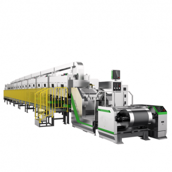
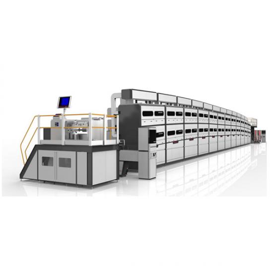
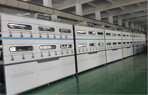
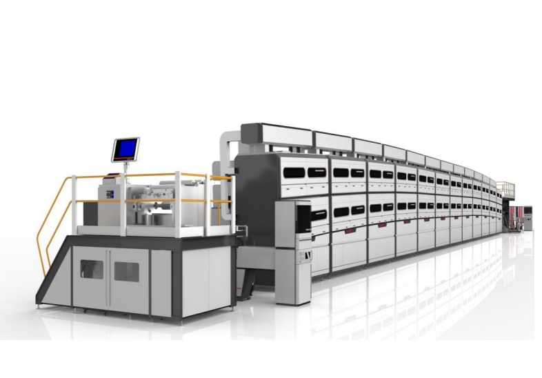
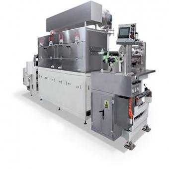
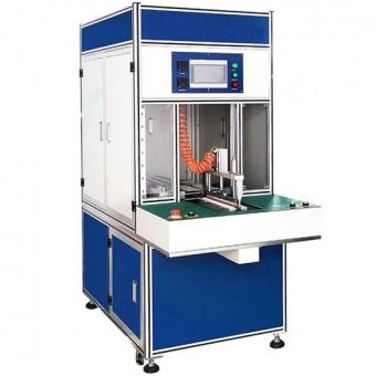
Automated Double Sided B-Type Coating Machine Lithium Battery Production Coater Machine
Basic functions of the device
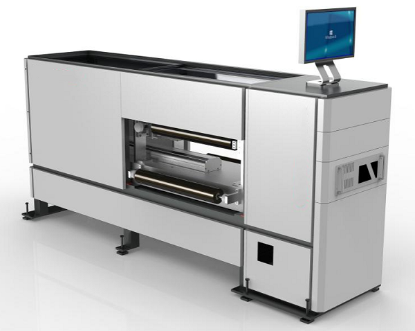
This equipment is used to unwind and transport the substrate to the coating mechanism through
the unwinding mechanism. The slurry is smoothly transported to the coating extrusion die under
a certain pressure through the feeding system. The slurry is sprayed onto a single side of the
substrate (copper or aluminum foil) through the extrusion grinding lip. The coated substrate and
slurry are pulled by the device driving mechanism to the drying box for drying. The dried material
is then driven and rolled back. Single sided coating, tandem double-sided coating machine.
Characteristics of the equipment
1. Digital tension: The unwinding, rear drive, and rewinding tension can be digitally set on the touchscreen, and the results of the three tension segments can be displayed simultaneously on the touch screen. The adjustment of tension is very convenient, and the smoothness of baseband operation can be clearly understood on the touch screen.
2. Servo with brake: The servo motor with distance control between the mold head and the base wheel is added to the brake, which can eliminate changes in the power-off time distance, thereby reducing the adjustment time.
3. Interrupt control: All places that require speed in a timely manner adopt interrupt control. The result of interrupt control reduces the error in coating length and alignment.
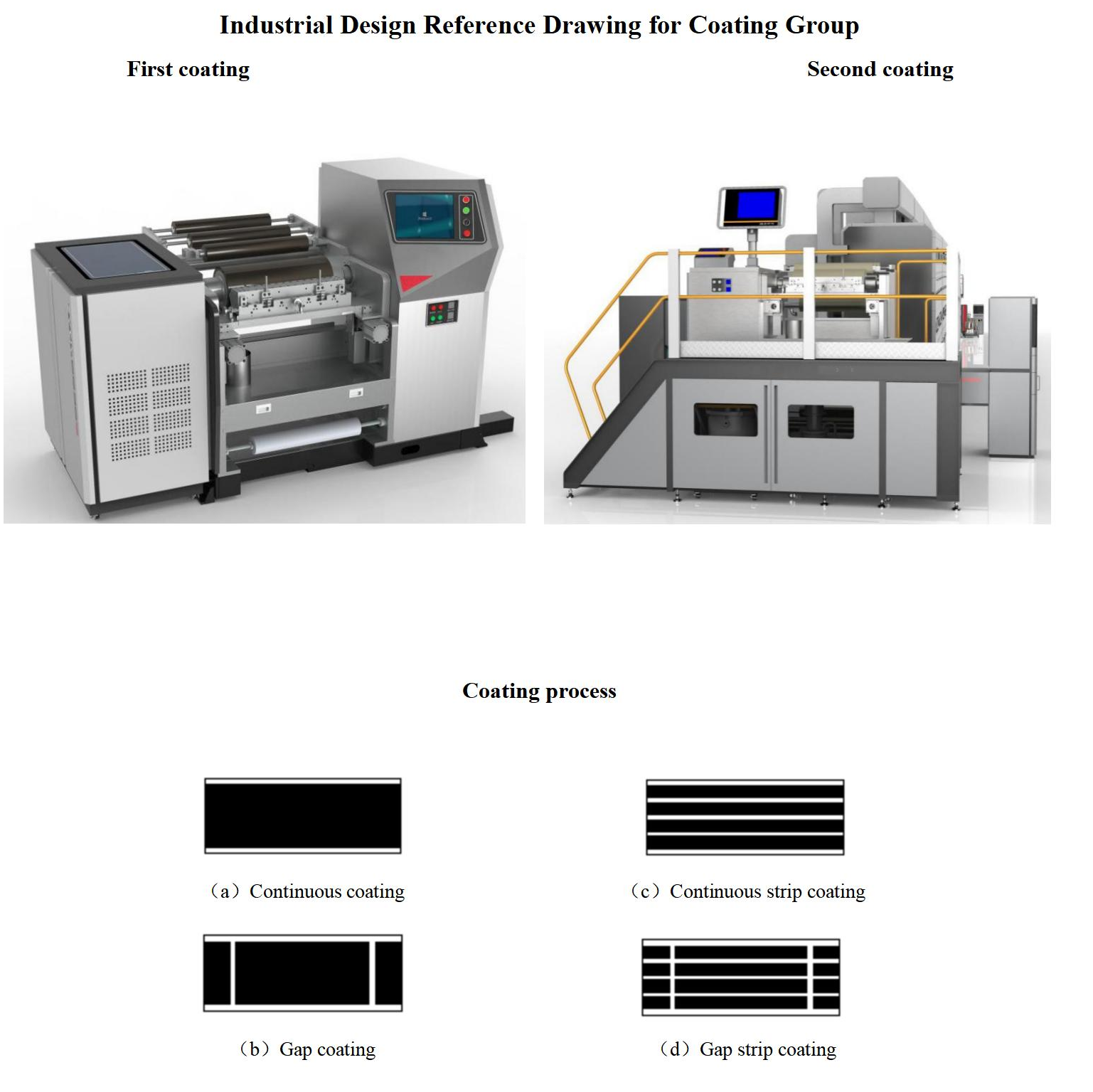
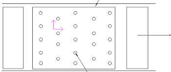
4. Strip coating: Adopting a custom mold head instead of a standard mold head to reduce slurry loss caused by gasket chamfering, making it easy to operate. For strip coating, the edge thickness can be adjusted according to user requirements.
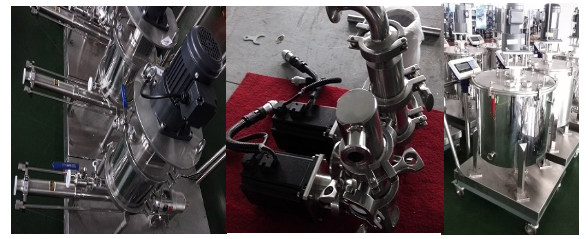
5. Dynamic filtration system: With a special filter structure, it can effectively filter out various impurities and is suitable for liquids of various viscosities. The equipment has good reliability, long maintenance cycles, and low maintenance costs. Compact structure and small footprint. Large filtration capacity per unit area, strong processing capacity, and can be filtered at multiple levels.
Hardware and functional description of the device
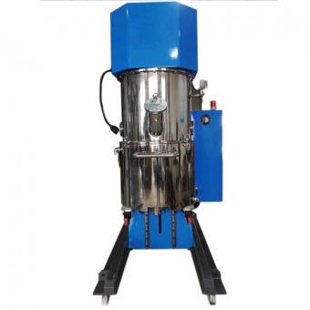
1. Feeding system: low-speed running slurry mixing tank+Japanese Bing Shen servo pump+servo motor drive+stainless steel pipeline. The main function is to dynamically store and smoothly transport slurry to the filtration system, ensuring that the slurry remains constant at a certain temperature.
2. Filtering system: The core technology of the I series (external scraper type) continuous scraper filter lies in its filter screen and scraper assembly. Each wire cross-section of this wedge-shaped filter screen is triangular, and the outer wall of the filter screen is smooth, which is beneficial for the scraper to remove impurities attached to it. The outside of the filter screen has a triangular opening, so that debris smaller than or equal to the required filtering accuracy will not get stuck on the filter screen, ensuring that the filter always maintains a good working state. When the scraper scrapes over the outer surface of the filter screen, it smoothly scrapes off the blockage on the surface of the filter screen, ensuring that the filter screen remains unobstructed at all times. The large particles intercepted by the scraper from the surface of the filter screen enter the waste chamber and are discharged regularly.
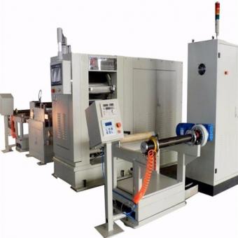
3. Coating machine: unwinding mechanism+coating mechanism+drying+secondary coating mechanism+rear driving mechanism+automatic winding mechanism. Its main function is to evenly coat the slurry on the substrate (copper foil and aluminum foil), dry it, and then wind it up.
Software and Function Description
1. The frequency converter and temperature controller both adopt communication control mode, and all fan frequency regulation and temperature setting can be centrally completed on the touch screen, without the need to open the control cabinet for adjustment.
2. The coating function is displayed and adjusted on the touch screen
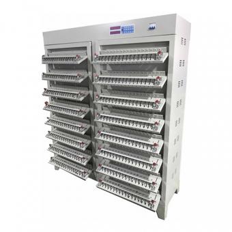
3. The surface density detection and coating mechanism form a closed-loop control, and the data storage and processing are detailed in the description of the surface density detection equipment.
4. The user provides a network on-site, and our company can achieve remote debugging function.
5. MES system interface shall be reserved for the equipment to facilitate the collection and management of production quality data.
6. If the seller's individual equipment involves upstream and downstream process connections, the user needs to adapt to the upstream and downstream equipment.
Technical specifications
I. Main components of the coating machine:
1. Unwinding mechanism: 1 set
2. Coating mechanism: 2 sets
3. Drying mechanism (double layer): 10 sets
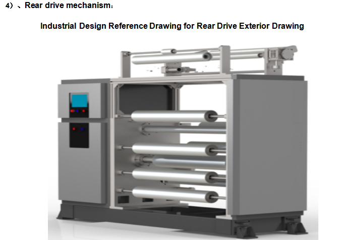
4. Rear drive mechanism: 1 set
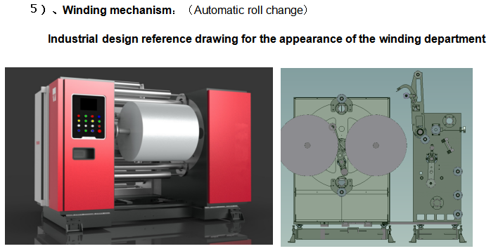
5. Winding mechanism (automatic roll changing): 1 set
6. Electrical control system: 1 set
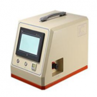
7. Thickness gauge (dry thickness): 1 set
II. Configuration of key equipment components:
|
No.
|
Name
|
Brand
|
Place of origin
|
|
1.
|
Coating head mechanical components
|
|
2.
|
Coating die head
|
Ningde Zhongneng
|
Customized according to customer requirements
|
|
3.
|
Coating roller
|
40Cr+electroplated hard chromium
|
Equipped with Japanese NSK bearings
|
|
4.
|
Front drive roller
|
40Cr+electroplated hard chromium
|
Equipped with Japanese NSK bearings
|
|
5.
|
Guide roller
|
Shenyanda Customization (Aluminum Alloy Surface Anodization)
|
domestic
|
|
6.
|
Coating mechanism guide rail
|
PMI/TBI
|
Taiwan
|
|
7.
|
Coating mechanism ball screw
|
PMI/TBI
|
Taiwan
|
|
8.
|
Coating roller and front drive roller bearing
|
NSK/NTN
|
Japan
|
|
9.
|
Displacement sensor
|
Panasonic/Delta
|
Japan
|
|
10.
|
Pneumatic components
|
|
11.
|
Die head propulsion cylinder
|
SMC
|
Japan/Taiwan
|
|
12.
|
Electrical proportional valve
|
SMC
|
Japan
|
|
13.
|
Pneumatic components
|
AIRTAC
|
Taiwan
|
|
14.
|
Motor and reducer
|
|
15.
|
Coating roller and front drive roller servo motor
|
yaskawa
|
Japan
|
|
16.
|
Coating roller, front drive reducer
|
Alpha/Newcastle/Xinbao
|
Germany/Japan
|
|
17.
|
Reel winding reducer
|
Liming
|
Taiwan
|
|
18.
|
Oven roller motor
|
Liming
|
Taiwan
|
|
19.
|
Fan
|
Stainless steel, multi wing low noise
|
Guangzhou
|
|
20.
|
Deviation correction and tension system
|
|
21.
|
Fully automatic deviation correction
(Winding and unwinding and process correction)
|
Aibo/Yuze/Dongdeng
|
Shenzhen/Shanghai/Chongqing
|
|
22.
|
Tension sensor
(Winding and unwinding, process tension)
|
Aibo/Yuze
|
Shenzhen/Shanghai
|
|
23.
|
Electrical components
|
|
24.
|
PLC
|
Panasonic/Huichuan
|
Japan/Domestic
|
|
25.
|
PLC digital/analog module
|
Panasonic/Huichuan
|
Japan/Domestic
|
|
26.
|
touch screen
|
HEYTEK/VIRON
|
Taiwan
|
|
27.
|
Temperature controller
|
Omron
|
Japan
|
|
28.
|
Color code sensor
|
SICK
|
Germany
|
|
29.
|
inverter
|
Tai'an/Yaskawa
|
Taiwan/Japan
|
|
30.
|
miniature circuit breaker
|
chint
|
France
|
|
31.
|
contactor
|
chint
|
France
|
|
32.
|
Intermediate relay
|
chint
|
France
|
|
33.
|
Thickness gauge (dry thickness)
|
Dual/RUIQI
|
domestic
|
|
34.
|
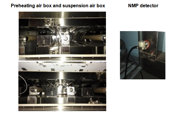
NMP concentration alarm
|
Gastron
|
Korea
|
|
If there are special circumstances, use the same level of brands mentioned above.
|
III. Usage conditions, basic functions, and technical indicators:
|
No.
|
Project
|
Technical Parameter
|
Notes
|
|
1.
|
Slurry system and substrate
|
|
2.
|
Suitable for slurry system
|
1. Positive pole: Lithium iron phosphate, lithium cobalate, lithium manganate, ternary and other oil-based or water-based systems.
2. Negative electrode: oily or water-based systems such as graphite; Super capacitors and related slurry systems.
|
|
|
3.
|
Suitable for slurry viscosity
|
Oily solvent 2000-8000 Cps
|
Intermittent coating
|
|
|
|
Aqueous solvent 2000-6000 Cps
|
|
|
|
|
1000~10000 Cps
|
Continuous coating
|
|
|
Suitable for solid content of slurry
|
Positive electrode slurry
|
35%~75%
|
PVDF system
|
|
|
|
Negative electrode slurry
|
S.c.30%~65%
|
PVDF system
|
|
|
|
|
s.c. 30%~65%
|
SBR system
|
|
4.
|
Solvent characteristics
|
Oily solvent NMP (s.g=1.033, b.p=204 ℃)
Aqueous solvent H2O/NMP (s.g=1.000, b.p=100 ℃)
|
For reference only
|
|
5.
|
Suitable substrate thickness
|
Al foil(Al): 8~30um Cu foil(Cu):4.5~30um
|
|
|
6.
|
Suitable for substrate width
|
350~670mm
|
|
|
7.
|
Mechanical characteristic indicators
|
|
8.
|
Design width of roller surface
|
750mm
|
|
|
9.
|
Guide roller outside the drying channel
|
about Ф 120mm aluminum guide roller with hard oxidation on the surface
|
finish≤0.8
|
|
10.
|
Equipment mechanical operating speed
|
1-60m/min
|
Infinitely adjustable
|
|
11.
|
Maximum coating speed
|
10-35m/min,depending on the slurry system and drying conditions
|
|
|
12.
|
Full range tension of the entire machine
|
3~25Kg.f,tension fluctuation±2%
|
|
|
13.
|
Basic function
|
|
14.
|
Extrusion coating method
|
Intermittent coating
|
Front 3 Unequally spaced Intermittent Coating/Back Automatic Tracking Front and Unequally spaced 3 Section Coating
|
|
|
|
|
Continuous coating (including strip coating method)
|
Infinite length coating
|
|
|
15.
|
Baseband operation mode
|
Single sided intermittent
|
Operation mode during intermittent front coating
|
|
|
|
|
Double sided intermittent
|
Operation mode during intermittent reverse coating
|
|
|
|
|
Continuous coating
|
Continuous and uninterrupted coating method
|
|
|
|
|
Wearing straps
|
The method of uncoating the empty belt
|
|
|
|
|
Rewind
|
Rewind operation mode during the first test piece inspection
|
|
|
16.
|
Thickness reduction function
|
During intermittent coating
|
Can eliminate thickness at the beginning and end of the coating section
|
|
|
17.
|
Alarm function
|
Sound, light, and text alarm
|
When the device malfunctions, the touch screen prompts the location of the fault and there is an audible and visual alarm
|
|
|
18.
|
Coating accuracy technical indicators
|
|
19.
|
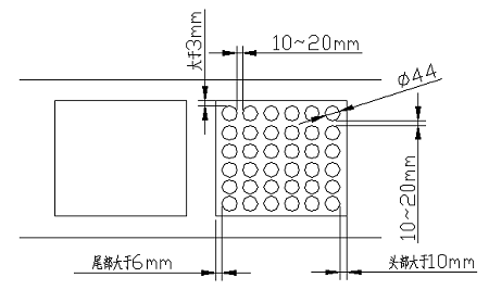
Coating section length error
|
± 0.5mm
|
|
|
20.
|
Width error
|
± 0.5mm
|
|
|
21.
|
Positive and negative alignment error
|
± 0.5mm
|
|
|
22.
|
Minimum intermittent length
|
6mm
|
|
|
23.
|
Minimum coating length for multiple segments
|
50mm
|
|
|
24.
|
Single sided coating dry thickness range
|
40-200μm
|
Related to material D50
|
|
25.
|
Coating surface density error
|
±1.3% (Single piece single sided)
±1.2% (two-sided)
Remove the influence of poor substrate; But the measured value includes the weight of the substrate;
|
Excluding edge impact areas
Substrate error ≤ 1% (single piece)
|
|
26.
|
Deviation correction accuracy of winding and unwinding
|
± 0.5mm
|
|
|
27.
|
Electrical specifications
|
|
28.
|
Source
|
3~380V/50HZ(Three phase five wire)
|
|
|
29.
|
Total installed power
|
1200KKW
|
|
|
30.
|
Oven heater power consumption
|
22*50Kw=1100KW
Power consumption after constant temperature: less than 660 KW
|
External electric heating
|
|
31.
|
Compressed air
|
≮0.6MPa Clean compressed air;
Gas consumption:0.5M3/H
|
|
|
32.
|
Equipment dimensions and weight
|
|
33.
|
External dimensions
|
Length (11 * 5M+12M+1=68M) * Width (3.5M) * Height (4.5M)
|
|
|
34.
|
Total weight
|
About 65 tons
|
|
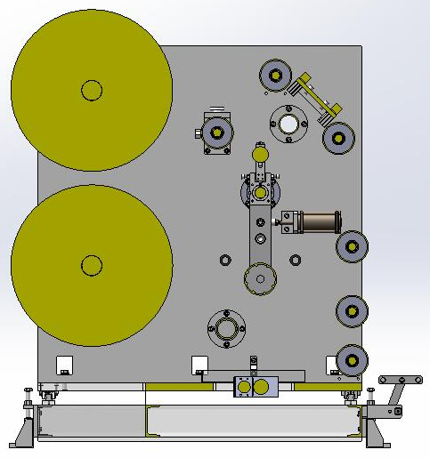
IV.Introduction to the Structure of Each Part:
1)、Unwinding mechanism:
 en
en fr
fr de
de ru
ru es
es pt
pt ko
ko tr
tr pl
pl th
th


 IPv6 network supported