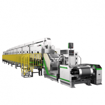
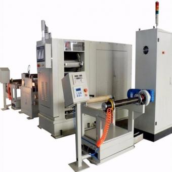
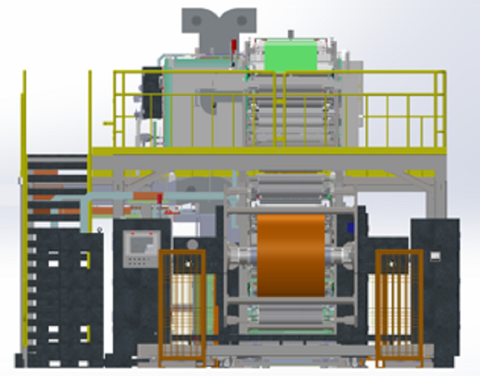
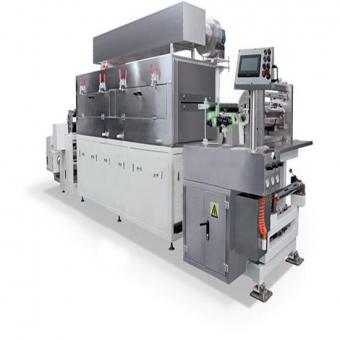
Double Layer Extrusion Coating Machine For Prismatic Cell Manufacturing
1. Equipment Overview
1.1Device Functions
The HJSC1000ZZ series coating machine is a new type of high-precision, reliable, and stable double-layer extrusion coating machine that our company needs to develop for power lithium batteries. The equipment features: high precision extrusion die head is selected, high precision displacement sensor and servo closed-loop control are adopted for die head, high precision Screw pump is selected, and medium is transported accurately and quantitatively; The oven adopts electric heating/steam heating, active roller+upper and lower blowing air suspension method; The coating machine uses an Omron PLC control system, which can achieve precise control according to process requirements; Digital control of polar tension, constant tension unwinding, constant tension coating, drying, taper tension winding; The system parameters are centrally controlled, and the human-machine interface adopts touch screen mode and hierarchical control. The process parameters can be locked, stored, and called.
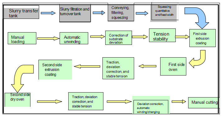
1.2 Running process
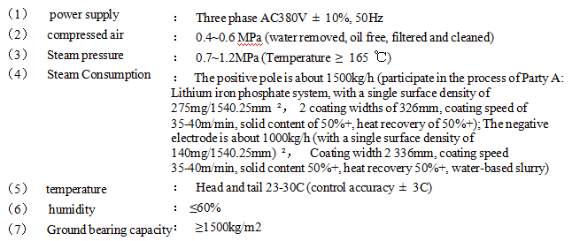
1.3 Population parameter
(1) Roll surface width: 1000mm
(2) Coating width: Max.800mm
(3) Mechanical speed: Max.60m/min
(4) Coating speed: Max.40m/min
(5) Rewind speed: 5-15m/min (rewinding without correction function)
The actual coating speed depends on the slurry system, slurry parameters, coating parameters, drying conditions, and product quality requirements The relevant three-phase asynchronous motors on the equipment adopt secondary energy efficiency.
(1) The columns and frames are made of carbon steel material;
(2) The stair treads and platform panels are made of SUS201 stainless steel patterned plates, and the guardrails are painted with carbon steel paint - yellow;
(3) One staircase entrance on side A and one staircase entrance on side B;
(4) The guardrail is welded and then fixed by bolts and platforms
7
Two sided furnace climbing guide roller system
1 set
8
Two sided discharge electrode plate guide roller system
1 set
Including 1 set of travel correction and several guide rollers
9
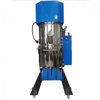
Coating and feeding system (including mixing drum, pump, filter valves, etc.)
2 sets
Precision Screw pump; 100L single-layer slurry barrel, motor stirring
10
Electronic control system
1 set
Omron PLC system
11
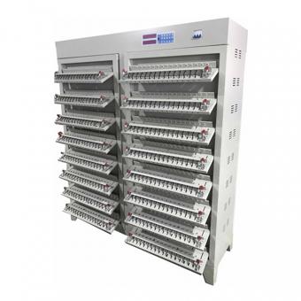
NMP concentration detector
8 sets
Positive electrode coating machine configuration
12
Edge ceramic coating feeding system
2 sets
Positive electrode coating machine configuration, designed according to four layers of adhesive coating
13
Double rack type β- Ray surface density detector (longitudinal closed-loop control with Screw pump)
1 set
Configure two sets of display screens, each installed at the coating area of the machine head and tail, to monitor the density of the opposite side
14
CCD alignment detection system (brand: OPT)
2 sets
Installed separately at the heads of the first and second coating machines, with a configuration of 8K high
3 Installation requirements
4 Equipment adaptation parameters
4.1 Substrate parameters
Project
Positiveelectrode
Negative electrode
Base material
Aluminum foil
Copper foil
Width (mm)
400-800
400-800
Thickness (µ m)
6-20 (Acceptance using 9um and above foil material)
4-15 (acceptance using 6 μm and above foil material)
Outer diameter (mm)
Max.800
Max.800
Weight (kg)
Max. 1500
Max. 1500
4.2 Slurry parameters
Project
Positiveelectrode
Negative electrode
Solute
Lithium Iron Phosphate
Graphite
Solvent
NMP
DI-water
Solid content
50-85%
45-60%
Proportion
1.5-3.0
1.0-2.0
Binder
PVDF
SBR
Viscosity (mPa. s, 25C)
5,000-20,000
1,500-8,000
Temperature (℃)
20-28
20-28
4.3 Coating parameters
Project
Positiveelectrode
Negative electrode
Single sided wet thickness (µ m)
80-280
60-200
Single sided dry thickness (µ m)
50- 150
50- 150
Single sided dry film weight range (g/㎡)
80~220
50~150
Coating width (mm)
Max.800
Max.800
5 Coating process parameters
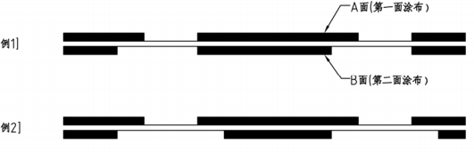
5.1 Gap coating diagram
(1) As shown in Figure 1, if the coating length on side A is different from that on side B, the longer side of the coating (side A) needs to be used as the first coating.
(2)If the starting position of the coating on side B is lower than the starting position of the coating on side A, the length of the coating on side B cannot exceed that of the coating on side A.
(3)In principle, the starting position of coating on side A and side B should be consistent (see Example 1).
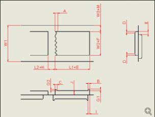
5.2 Gap coating accuracy
Project
Mark
Standard (coating speed ≤ 30m/min)
A (trailing)
≤ 1mm (related to slurry properties)
B (abnormal head area)
≤ 5mm (related to slurry properties)
C (tail abnormal area)
≤ 5mm (related to slurry properties)
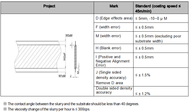
D (Edge effects area)
≤ 5mm (related to slurry properties)
E (length error)
≤±0.5mm
F (width error)
≤±0.5mm
M (width error)
≤±0.5mm
G1 (thickness error of one side of the head)
- 10~5um (Related to the characteristics of the slurry)
G2 (Thickness error on one side of the tail)
- 10~5um (Related to the characteristics of the slurry)
H(Blank error)
≤±0.5mm
I(Front and back longitudinal position error)
≤±0.5mm
K(Lateral position error of front and back sides)
≤±0.5mm
JSingle sided density accuracy (excluding areas B, C, and D)
≤±1.5%
Double sided density accuracy (excluding areas B, C, and D)
≤±1.2%
Coating/Intermittent length
L1 (film length)
50~20,000mm
L2 (intermittent length)
6~500mm
L1+L2 (coating+gap length)
L1 +L2≥60mm
※ The minimum coating length and minimum coating gap depend on the coating speed, with a 10mm gap corresponding to a coating speed of 20-25m/min.
※ The contact angle between the slurry and the substrate should be less than 40 degrees.
※ The viscosity change of the slurry per hour is ≤ 300cps.
5.3 Continuous coating accuracy
6 Equipment specifications and parameters
6.1 Roller parameters and accuracy
(1)Roller specifications and accuracy
Specifications
Roller Diamter
Surface treatment
Runout(mm)
Surface roughness
Material
Coating back roller (metal roller)
φ295
Hard chromium plating ≥ 200 μ M
0.001
Ra0.2
40Cr
Guide roller (metal roller)
φ110
Hard oxidation
0.02
Ra0.4
Al
Traction roller (metal roller)
φ200
Hard chromium plating ≥ 100 μ M
0.005
Ra0.4
S45C
Pressure roller (rubber roller)
φ135
Wrapped EPDM rubber
0.1
---
Al or SS400
(2)Roll assembly accuracy
Specification item
Parallelism(mm)
Between metal rollers (outside the oven)
0.05
Between metal rolls and metal rolls (inside the oven)
0.1
Between metal roller and rubber roller
0.2
Specification item
Levelness (mm/m)
Metal roller (outside the oven)
0.05
Metal roller (inside the oven)
0.1
Rubber roller
0.2
6.2 Automatic unwinding unit
No.
Project
Technical parameter
Notes
1
clamping system
Inflation clamp tightening
2
Roll changing method
Rotary tower automatic roll changing, automatic cutting, tape splicing
Glue pressing roller overlapping and gluing
3
Unwinding diameter
Max Ф 800mm
4
Inflation clamp
6 inches, with a load-bearing capacity of Max.1500Kg
The expansion sleeve of the inflation clamp adopts special wear-resistant rubber
5
Unwinding drive
Servo motor+precision reducer
6
Material barrel
6 inches, length 1100 ± 5mm
Material: ABS or stainless steel
7
Rotating tower device
Rotating tower speed 1r/min
The turret drive adopts a motor+precision return
Flip positioning accuracy: height error H ± 5mm
Drive by rotary reducer, achieve high-precision position control through servo encoder
8
Center height of the turret
1500mm
9
Tension control system
Low friction cylinder+proportional valve control tension, tension sensor feedback adjustment range of 40-300N, tension fluctuation of ± 1% FS
Constant tension control
10
Deviation correction method
Automatic EPC control, stroke ± 50mm, using ultrasonic sensor, gradual speed regulation and deviation correction, accuracy ± 0.1mm
Adaptable transparent substrate guide tape
11
Knife swinging arm mechanism
1) Sawtooth cutting blade, with a cutting life of ≥ 5000 times;
2) There is a pneumatic protective cover in front of the cutting knife, which can be covered when not working to prevent scratching personnel
12
Loading method
AGV
13
Roll diameter measurement
Ultrasonic testing, alarm according to the set coil diameter
14
Takeover platform
1) Adopting double pressure rods, but manually connecting the platform in the form of scratch grooves;
2) There is a rubber strip at the bottom of the pressure rod to avoid direct contact between the metal and the surface of the electrode plate
Bottom configuration dust collection box
15
Running direction
Up or down, only downward when automatically changing rolls
16
Belt routing method
Forward traction, coating, reverse rewinding
17
Polar iron removal
Two sides of the substrate are equipped with magnetic rods, with magnetism ≥ 10000GS
18
control system
1) Set up functional operation buttons and touch screens in the unwinding section. 2) Ultrasonic sensors monitor the coil diameter and have the function of calculating the coil diameter and reminding of material shortage
Can display coating length and machine head control information
19
Safety devices
1) There is guardrail+Light curtain at the turret;
2) Pull rope switch plays an emergency stop role;
3) When there is an opposing switch under the inflation clamp and there is no AGV or hydraulic trolley, the inflation clamp is not allowed to retract
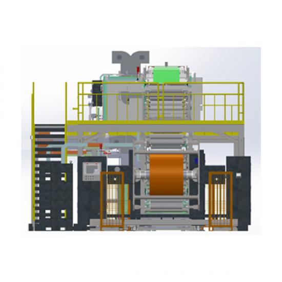
6.3 Coating unit
No.
Project
technical parameter
Notes
1
Installation structure method
Thickness 60 mm+overall vertical plate structure, wall panels plated with hard chromium
2
Coating method
A/B series type, continuous coating/gap coating/stripe coating
3
Coating roller (steel roller)
¢295mm, surface plated with hard chromium, circular runout: ≤ 1.0 µ m (micrometer detection), power: DDR motor (Colmorgan)
Surface finish Ra0.2
4
Pinch roller device
Diameter: ¢135mm, material: SS400+EPDM, Shore hardness ≥ 75 degrees; Double cylinder compression, eccentric wheel adjustment for left and right compression force
5
Extrusion head
1. High precision extrusion head (2 sets/line), adjustable lip;
2. The coating width is Max.800mm, and the coating width can be adjusted by replacing the gasket;
3. The mold head is equipped with an online flipping mechanism, which can be used for online flipping and cleaning of the mold head
Parallelism between extrusion die head and coated steel roller ≤ 5 μ m. Lip straightness ≤ 3 μ m. Flatness ≤ 3 μ m. Attached inspection report
6
Spacer
4 pieces/set, thickness error accuracy ± 2 μm
7
Disposal of leftover materials
Funnel plate for installing leftover materials at the bottom of the mold head
8
Extrusion head base
A: Die base forward and backward drive:
1. Large stroke moving cylinder drive (cylinder with protective cover to prevent slurry pollution); 2. Gap fine adjustment: servo motor action, high-precision displacement sensor measurement, resolution 0.1 μm. Repetitive positioning accuracy ≤ 0.3 μm. Feed time ≤ 10s;
There is an anti-collision design between the extrusion head and the steel roller;
The operation screen page displays the set value and actual value
9
Feed pump
High precision metering feed pump
Japanese War God
10
Turnover bucket
(1) Volume: 100L, made of stainless steel 304, with polished inner and outer surfaces, in a single layer; (2) Equipped with a corrosion-resistant liquid level probe, with 4-speed display (highest, high, low, lowest). When the liquid level of the coating material tank is lower than the lower limit liquid level, the automatic feeding is turned on. If the liquid level does not exceed the lower limit after a few minutes (set on site), the equipment will automatically alarm; (3) Electric stirring, adjustable speed; (4) With visualization window
The slurry bucket is equipped with a visualization window, and the feeding port is anti splashing to prevent the generation of bubbles
11
Filter iron removal
Two stage metal filter+10000GS iron remover - filter the feeding (100 mesh filter element) and Screw pump outlet (150 mesh filter element) of the container
12
Scraping and hole detection
After the coating roller, a light curtain is installed to detect holes caused by scraping of the electrode strip, and timely alarm is given, with manual judgment of whether to stop the machine for processing
13
Adhesive tape level detection
Configure a color code sensor for tape level detection before entering the coating process, and achieve linkage with the coating system to achieve skip coating of the tape level
14
Coating valve
Gap coating valve group
15
Pressure monitoring unit
Pressure inside the extrusion head chamber and pump outlet (pressure
Set aside corresponding analog output interfaces for computer collection of pressure data
16
Tension control system
Digital tension adjustment mode/five segment tension control, touch screen setting and monitoring of tension value
17
Die head lateral fine adjustment mechanism
Driven by a servo motor and a screw, it can be closed-loop controlled with a CCD size detection system to ensure alignment of the AB surface
6.4 Edge ceramic coating system
No.
Project
Technical parameter
1
Type
The Screw pump is used for centralized feeding. The dispensing method is to set a special ceramic feed hole on the die head and make a ceramic flow channel on the gasket; Screw pump brand: Nippon Bingshen, 2NBL10F
2
30L slurry bucket
Made of stainless steel 304 with polished inner and outer surfaces; Volume 30L, single layer; Motor stirring, adjustable speed
3
Thickness control
Control by adjusting the opening of the throttle valve
4
Filter
Metal straight through/Y-shaped filter with 100 mesh core
5
Feed pipeline
Stainless steel SUS304 pipe+Teflon pipe
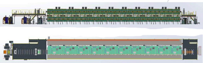
6.5 Oven unit
No.
Project
Technical Parameter
Notes
1
Type
Full main transmission, 5 meters per section, with a total of 40 meters for both the upper and lower parts; 0.5 meters each for the front and rear negative pressure chambers
The total length of the oven is approximately 41m above and below each
Three phase motor frequency conversion control is adopted, and guide rollers are horizontally distributed; The surface of the guide roller is plated with hard chromium, with a diameter of ¢ 110mm
The internal bearings of the oven adopt high-temperature resistant bearings
4
Air nozzle height adjustment
The overall lifting adjustment of the air chamber, with an adjustment amount of ± 20mm
5
Observation window and access door
1) Each section of the oven is equipped with 3 visual observation windows
2) Reserved maintenance and cleaning door on the transmission side of the oven
6
Heating method
Steam heating, steam pressure ≥ 0.7MPa
7
Oven temperature
50~140℃
8
Oven temperature control
(1) Independent PID adjustment for each section of the oven;
(3) Normal working temperature control, overtemperature monitoring alarm protection control, when overtemperature occurs, an audible and visual alarm will appear, and the steam source will be cut off
9
Temperature control accuracy
Display accuracy: ± 1 ℃ (difference in indicated value of temperature control meter);Control accuracy: ≤ ± 3 ℃ (excluding the first and last sections)
10
Surface temperature of the box during operation
The external temperature of the oven is ≤ room temperature+20 ℃ (process temperature ≤ 135 ℃)
Excluding door joints, flange joints, glass windows, and the connection between two ovens
11
Diaphragm blowing method
Up and down blowing, explosion-proof variable frequency motor for air supply; Common heating element for upper and lower air chambers
12
Air volume control
1) Circulating air volume, equipped with 1 circulating fan per section;
2) Adjust the frequency converter to control the air flow according to the process, and set the frequency conversion parameters on the touch screen; 3) Each section of the upper and lower air chambers is adjusted through mechanical valves and independently controlled;
4) The fresh air volume is adjusted by mechanical valves for each section and controlled independently; Fresh air is uniformly supplied by the factory;
5) The exhaust air volume is adjusted by mechanical valves for each section and controlled independently;
13
Pressure monitoring
Equipped with 4 sets of mechanical pressure gauges inside and outside the oven, air nozzles, and before and after filters
14
Fan
1) Circulating fan - power: 11kW; Air volume: Max.11000m3/h; Total pressure: Max.1200Pa
2) Inlet and exhaust fans - configured according to Party A's process and layout
The contact between the fan and the hot air is made of stainless steel material
15
Exhaust air volume
According to the LFP system, with a single surface density of 200g/㎡, a coating width of Max.800mm, a coating speed of Max.40m/min, and a solid content of 55%+, the exhaust air volume of the positive electrode machine is approximately 60000~70000 meters ³/ H (130 ℃ working condition); If the negative electrode has a single surface density of 100g/㎡, a coating width of Max.800mm, a coating speed of Max.40m/min, and a solid content of 50%+, the exhaust air volume of the entire water system negative electrode is about 40000~50000m ³ / H (110 ℃ working condition)
16
Hot air filtration
Configure initial efficiency filter before air intake
17
Explosion proof port
Each oven is equipped with explosion-proof ports
18
Linkage between positive electrode and NMP recovery system
(1) The manufacturer of the NMP recycling system connects the relevant cables and signal wires to the reserved interface of the coating machine, and sends the relevant operating signals and system abnormal signals (shutdown, fault alarm, shutdown) to the coating machine;
(2) The coating machine integrates the common functions of the NMP recycling system (start stop, air volume adjustment, etc.) into the touch screen of the coating machine head, and abnormal signals of the NMP recycling system can be displayed on the touch screen of the coating machine;
(3) When the NMP recycling system fails to start due to a malfunction, the coating machine prompts: The NMP recycling system is malfunctioning and cannot start the coating machine, and outputs a signal to the NMP recycling system;
(4) The coating machine can only be produced and operated when the NMP recycling system is running normally. When the system is abnormal, the coating machine cannot be produced and operated.
19
Oven NMP concentration monitoring
Positive pole configuration NMP concentration detector——
A. When the concentration exceeds 25%, the equipment will give an audible and visual alarm;
B. When the concentration exceeds 50%, the equipment stops running and coating, the circulating fan continues to operate, and the exhaust fan automatically operates at its maximum frequency
20
Drive Motor
A. Circulating fan: three-phase asynchronous motor........... 16 units
B. Roller drive: three-phase asynchronous motor ...............
16 units
6.6 Traction unit
No.
Project
Technical parameter
1
Installation structure method
Overall vertical plate installation
2
Traction tension control system
1) Cylinder+proportional valve control tension, tension sensor feedback
2) The adjustable tension range is 40-300N, and the tension fluctuation is ≤ ± 2% FS (during normal operation)
3
Tension partition
Composition of traction roller and pinch roller
4
Traction roller
Diameter Ø 200mm, surface plated with hard chromium
5
Pinch roller
Diameter Ø 135mm, surface coated with EPDM adhesive
6
Travel correction
1. Adopting EPC control, equipped with anti roll edge pressing roller and arc flattening roller at the outlet of the oven
2. EPC control, stroke ± 50mm, using ultrasonic sensor, gradual speed regulation and deviation correction, accuracy ± 0.1mm
7
Traction roller drive
Servo motor+precision reducer
8
Pole flattening mechanism
Flattening of electrode plates using curved rollers
6.7 Automatic winding unit
No.
Project
technical parameter
Notes
1
Clamping system
Inflation clamp tightening
2
Roll changing method
Rotary tower automatic roll changing, automatic cutting, tape splicing
Glue pressing roller overlapping and gluing
3
Reel diameter
Max Ф 800mm
4
Inflation clamp
6 inches, with a load-bearing capacity of Max.1500Kg
The expansion sleeve of the inflation clamp adopts special wear-resistant rubber
5
Winding drive
Servo motor+precision reducer
6
Material barrel
Inner diameter 6 inches, length 1100 ± 5mm
Material: ABS or stainless steel
7
Rotating tower device
Rotating tower speed 1r/min
Flip positioning accuracy: height error H ± 5mm
The turret drive is driven by a motor and a precision rotary reducer, and high-precision position control is achieved through servo encoder
8
Center height of the turret
1500mm
9
Tension control system
Low friction cylinder+proportional valve control tension, tension sensor feedback adjustment range of 40-300N, tension fluctuation of ± 1% FS
Taper tension control, adjustable from 0 to 80%
10
Deviation correction method
EPC control, stroke ± 50mm, using ultrasonic sensor, gradual speed regulation and deviation correction, accuracy ± 0.1mm
Adaptable transparent substrate guide tape
11
Knife swinging arm mechanism
1) Sawtooth cutting blade, with a cutting life of ≥ 5000 times;
2) There is a pneumatic protective cover in front of the cutting knife, which can be covered when not working to prevent scratching personnel
12
Discharge method
AGV
13
Roll diameter measurement
Ultrasonic testing, alarm according to the set coil diameter
14
Manual tape receiving platform
1. Adopt double pressure rods, but manually connect the tape platform in the form of scratch grooves;
2. There is a rubber strip at the bottom of the pressure rod to avoid direct contact between the metal and the surface of the electrode plate
15
Running direction
Up or down, only downward when automatically changing rolls
16
Winding alignment
≤±1.0mm
17
Polar iron removal
Two sides of the substrate are equipped with magnetic rods, with magnetism ≥ 10000GS
18
control system
1) Set up functional operation buttons and touch screens in the winding section. 2) Ultrasonic sensors monitor the diameter of the coil and have the function of calculating the diameter and reminding the completion of winding
Can display coating length and machine head control information
19
Safety devices
1) There is guardrail+Light curtain at the turret;
2) Pull rope switch plays an emergency stop role;
3) When there is an opposing switch under the inflation clamp and there is no AGV or hydraulic trolley, the inflation clamp is not allowed to retract
6.8 Electrical control system
(1) Main control system: touch screen, PLC, bus control, servo system, pressure monitoring system
(2) Wiring method: Bussed distribution, strong and weak current slot layout
(3) Electric control cabinet layout: independent dustproof cabinet, high and low voltage cabinet with separate box design
(4) Electric control method: decentralized layout, centralized control, high reliability, space saving, and easy maintenance
(5) Operation mode: manual, automatic, emergency stop; The main control system is located on the touch screen of the machine head; The tail can also be operated for general operations such as shutdown, belt running, emergency stop, etc
(7) Operating condition setting and data collection: coating line speed, tension control, coating setting, fan frequency, and temperature setting can be set, displayed, and recorded through the touch screen; Can store 20 sets of process parameters
(8) Status monitoring: Five stage tension monitoring, belt breakage monitoring, deviation correction, temperature monitoring
(9) Counting function: Measure the coating length in meters, with a display accuracy of 1mm
(10) Safety protection function: mechanical and electrical interlocking, self-locking function, induction protection function
Can; Alarm bells in each area before equipment startup; Set up safety warning signs for hazardous areas such as movement, compression, cutting off, and heat sources; Protective cover for transmission and moving parts; Oven over temperature alarm and power outage protection function
(11) Alarm situation: When the equipment malfunctions or starts, the three color alarm light on the machine head
Warning; There is a dedicated alarm buzzer for winding and unwinding; The touch screen will display the corresponding correction screen; Alarm information storage and historical alarm information viewing
(12) Control management: password hierarchical control, process parameters can be locked; Password is required for setting and maintaining device parameters
 en
en fr
fr de
de ru
ru es
es pt
pt ko
ko tr
tr pl
pl th
th


 IPv6 network supported